External Brief: Blog post 2
- albertfturner14
- Dec 7, 2021
- 5 min read
Drawing Analysis
Pamphlet / Booklet

Vessel
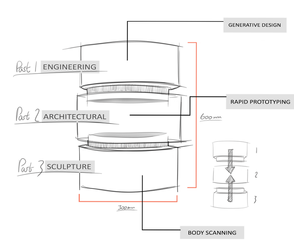
Initial Problem Seeking
Body scanner & blender

Size Teams SS20 Classic body scanner,
designed for taking measurements of the human body composition, the total amount of fat and muscle, lean tissue, fat-mass index (FMI) and lean-man index (LMI).
Primarily this is used to pinpoint a persons body fit in industry's such as fashion, athletics / body building and acting. Size Teams take pride in transforming the uniform fitting process with their body scanning technology. This use is what makes them so applicable in manufacturing uniforms, costumes and fashion clothing.
Although the SS20 Classic body scanner is useful to the fashion courses at AUB the modelmaking course has also found use for it.
With the data collected imported to a STL file we can 3d print a scan. I want to emphasise this in the document I produce for my client as its another way of making something digital physical as opposed to the traditional ways of CAD modelling.
However the first problem to my theory occurred in my induction with our course technician. He explained that the body scanner can only scan a person in their complete form when standing in a specific position. If they are not, or if your scanning an object then the cameras wont pick up all the data therefor leaving parts of the scan missing and leaving you with an uncompleted mesh which cant be 3d printed.
It was said in my induction that this problem can be fixed by using CAD software to remodel / fill in the missing parts.
Are two free to download CAD programs that can do this job.
Here is a list of some of the most popular CAD programs.
If you already have a preferred CAD programs then its always worth checking if they can do mesh work as well. Linkedin Learning through myAUB has plenty video tutorials on these programs.
Rhino
Solidworks
Fusion 360
3ds Max
Sketchup
These are all free to download if your a AUB student.
Fusion 360 and 3Ds Max are available on Autodesk. Uni student at AUB can access these CAD programs for free logging in with your student ID and password.
Knowing accessibility that AUB have for a range of CAD software's is critical for students. Further more understanding which is used for what in industry and knowing if AUB can extend their CAD licences commercially is critical information in the pamphlet.
This should help businesses and students gain an understanding of where they fit within the application of these 3d printer.

BODY SCAN
I exported this as an OBJ file and trimmed my body scan in Rhino leaving me with only the head bust.

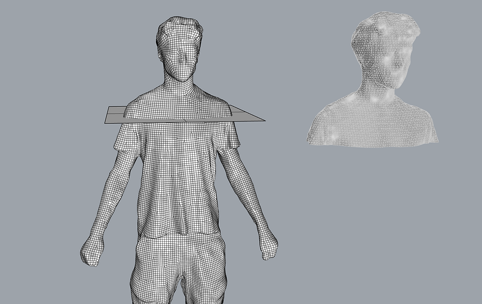
From there I imported it into blender.


Once I was familiar with the sculpting tools I got to work on refining details to my body scan.

It's easy to see that I didn't have much luck with this. The reason being the vertices to the mesh where too far apart thus meaning details such as eyes, ears, nose and mouth where imposable to sculpt in CAD.
I researched and attempted solutions to this problem and found a possible fixes though a YouTube tutorial. This explained the Remesh compared in blender however, whenever I attempted it myself my Laptop ended up crashing on me.
YouTube tutorial - 3D scan: Repair and Modify in Fusion 360
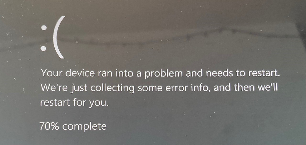
This may have been because the file was to large for blender to run the compared smoothly or the file was the wrong type, equally this could have had something to do with my laptops specs, most likely the CPU. However I was running out of time on this part of the project and needed to move on quickly.
It was at this point that I decided to take a different direction with my head bust.
Instead of making a realistic replica of myself I thought of using Instant meshes to crate a abstract bust instead.

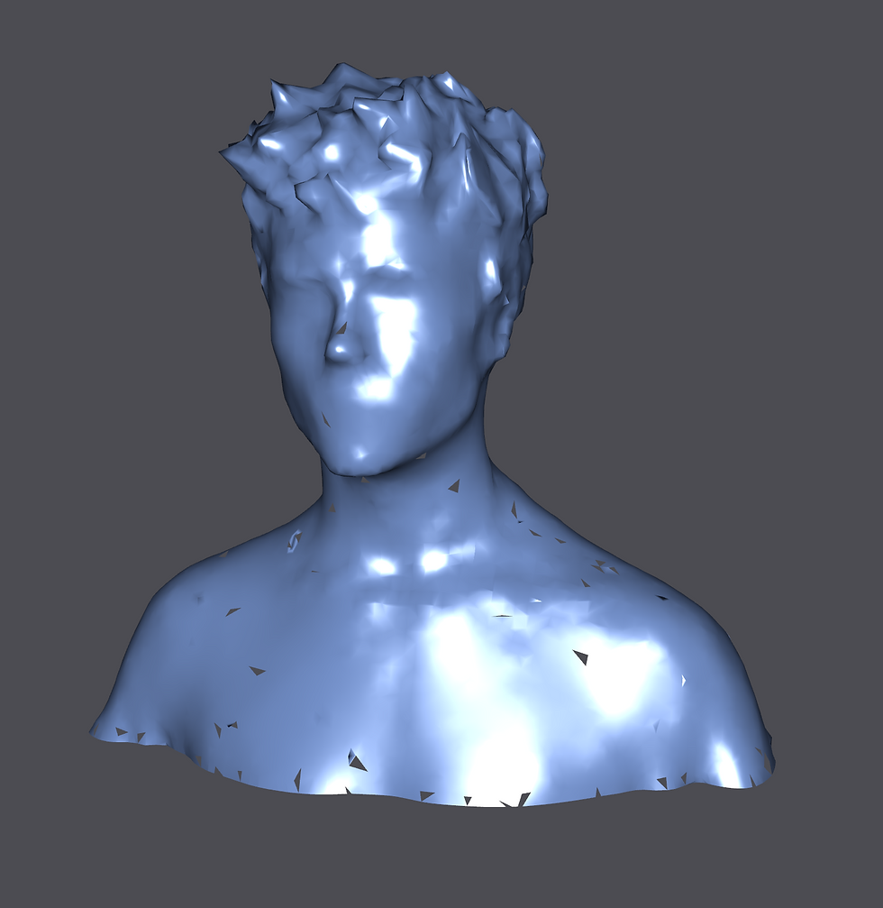
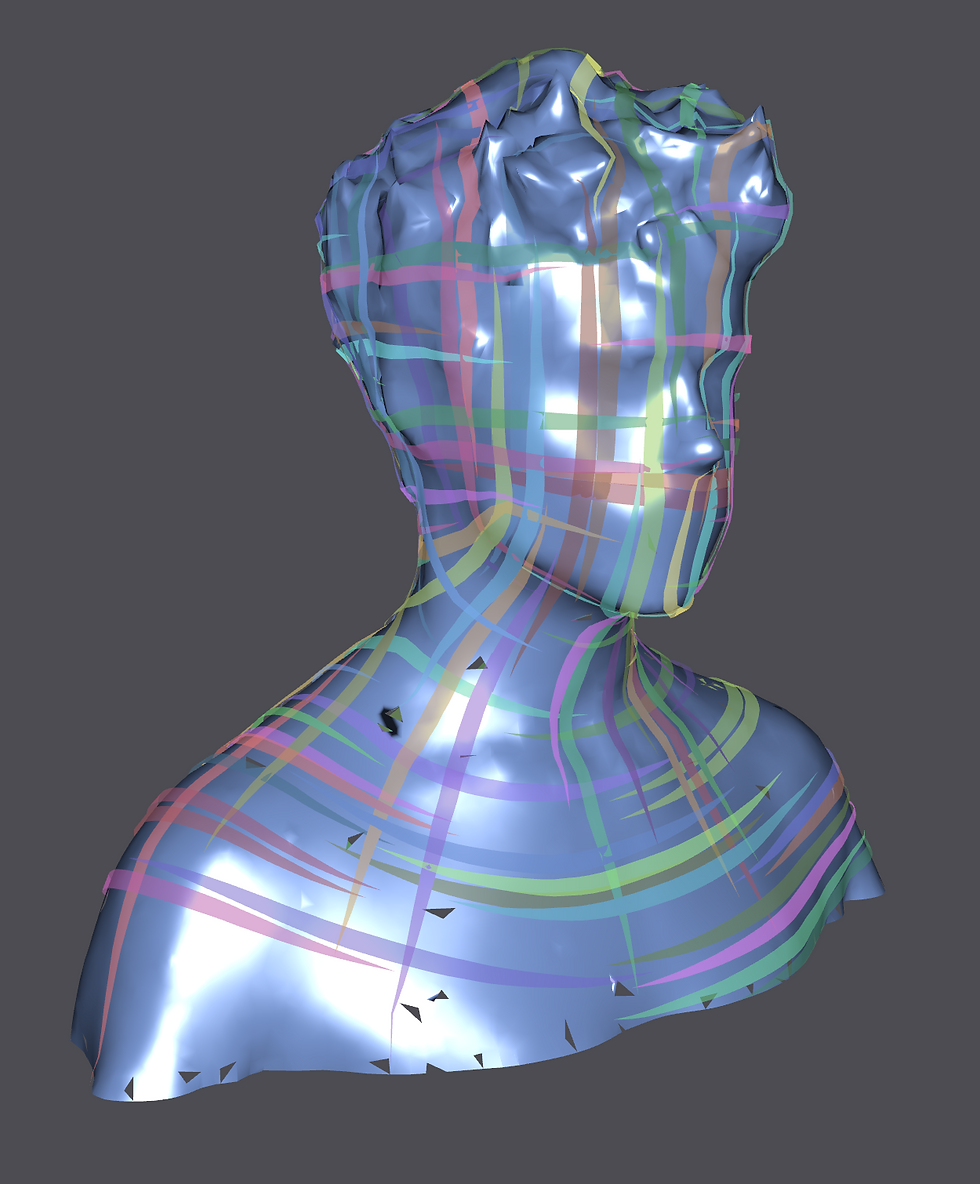

This worked well, and all that was needed was to import this into Rhino to trim the bottom so that it was flush. Then I exported the bust as a STL file ready to be printed on the Delta Wasp 3MT.
It was only after all this searching that I learned another posable solution to this issue through the body scanners end.
"Super-fast to measure surface measuring within +/- 5mm of precision".
"Customize measurement output to your company's specifications to prove a personalized experience for your customers". https://www.sizestream.com/technology
Theoretically if the settings where changed to the output of 1mm in procession there would be a higher vertices count, resulting in a denser mesh making this much easier to sculpt and posable to add fine details.
Although this stage of my project could have gone better, I acknowledge that it lead me on a different path than what I intended, and now understand where I should have started my investigation at the body scanners end.
However trial and error can have a way of making you learn more than if everything went smoothly. A lot can be reflected in my work flow timeline when I produce the pamphlet. Finding through my investigations different ways of manipulating your body scan using Instant meshes, as well as finding out a realistic replica can be achieved if we are able to change the settings on the body scanner.
Design Development
Chang of plan
It was at week 3 of the project that I was left with a difficult decision, as I wasn't going to leave major project altering decisions any latter. This is a habit that I've had to get myself into as it is not uncommon for me to act upon spur of the moment ideas. By revaluate the project earlier on I can take a step back and see the project in its perspective such as assessing how lone the first stage took.
In this case it look 4 days too long, which with everything considered is unrealistic to afford similar setbacks.
I decided to counteract this by using a CAD model I had already made in second year.
I decided to use the propellers as it would be a good example test piece for an engineered prototype printed on the Markforged Mark Two.
Also I could improve the CAD model by making the propeller spin manually.
This is a necessary feature to my example of a working prototype as the Mark Two specialises in printing parts that are fit for purpose strait of the desktop.
Progression photos of spinning propeller improvement
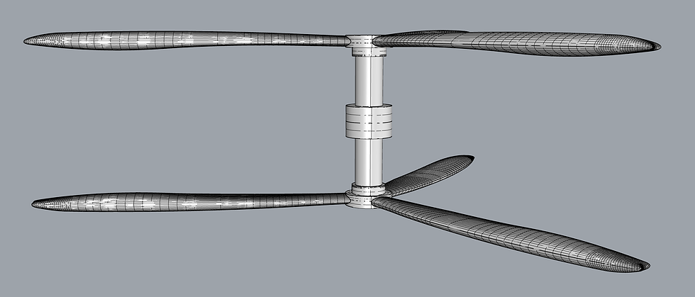


The design and prototyping process permits me to run my prints though cost affective first generation prints using the Ultimaker and Formfinder 3D printers. This is to ensure that any 3D modelling errors that where over looked, printing problems or simply finding more officiant ways of printing this part through adjusting some setting in the slicer software can be realised and dealt without wasting the expensive materials that the Mark Two prints with.
This is a necessary step as the Mark Two is a printer that's used for the final generations of a prototype. So there must be previous generations of this part documented in the pamphlet before we get to the stage of using the Mark Two for the fit for purpose prototype.
Drawing Interpretation
Printing a drone

It turns out that not as much will have to be sacrificed as I thought.
I can still employ the use of generative design by modelling a drone chassis in Fusion 360.
Through my research of generative design the process is not to time consuming.
Briefly I can explain, as the making of a part runs off algorithm's which dictates a form through structural constraints and structural loads, whilst preserving seitan geometry as well as making seitan geometry a obstacle for the form generated insuring they don't come into contact with one another.
The most appropriate generation will be printed on the 3MT.
This will be a good display of the 3MTs capabilities and restraints when it comes to printing something smaller and more intricate than the head bust.
I hope by doing this that I will be able to find an out line of The 3MTs capabilities which I can document in the pamphlet.
Break-down
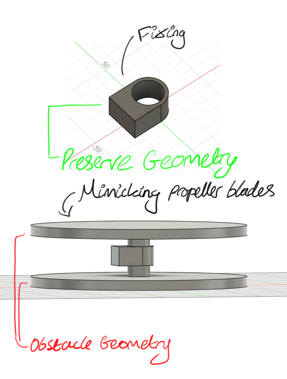

generating

Results


Comments