Major: planning & making
- May 20, 2022
- 5 min read

For my major I will be submitting the robot known as K-VRC from the series
Love, Death + Robots.
In the episode K-VRC is digitally animated along side his two companions XBOX 4000 "and an unnamed triangular bot with a flat electronic assistant's voice". In this episode their story begins a long time after ours in a post apocalyptic city, site seeing! they have supposedly evolved from our own technology and are just like us. The XBOX guy is obvious but K-VRC was once a baby monitor and no body knows what the triangular bot evolved from.
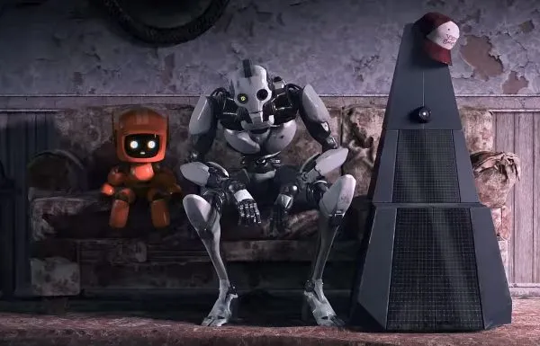
Image 1: Three robots
The creators of this animation are Blur Studio's however Love, Death + Robots is a world wide project with animation studios across the globe creating episodes for this series in their own individual styles.
My objective to make the digitally animated character K-VRC into a tangible stop motion puppet is exciting. Not only will I be exploring another new avenue to metalwork through armature making, I will also be progressing my modelmaking, creativity, problem solving and CAD skills. But I'm also exploring stop motion character making for the first time and I feel my ambition in this last unit has come true as the work I have done so far has been the highlight of these last couple of years!
What are the benchmarking requirements for a stop motion character in industry?
Bench marking
A stop motion character requires some specific features so that it can be animated.
Most importantly a stop motion character needs an armature. The armature is essentially the bones of the character giving it the movement it needs to be animated.
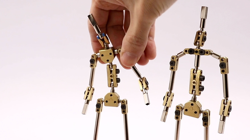
Image 2: Armatures.
Rigs and rigging points. These are used to support the characters positions. There are usually 3 or 4 rigging points to a character at the head, back, right & left.

Image 3: Rigging a stop motion character.
Keeping the screw holes in the ball & socket joints exposed so that they can be re-tightened. This ensures that the armature joints remain stiff so that the characters positions hold. Clothes or fur usually conceals the armature joints but I will need to find a different way as K-VRC doesn't have any clothes or fur.

Image 4: exposed knee joins.
Interchangeable features! Mechanical fixings, magnets and screws make facial expressions, hands and any accessories easy to interchange.

Image 5: Interchangeable faces
Key features
Animating eyes using the hole and needle method.
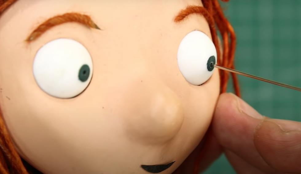
Image 6.
Animating hair concealing wire in each strand of hair.
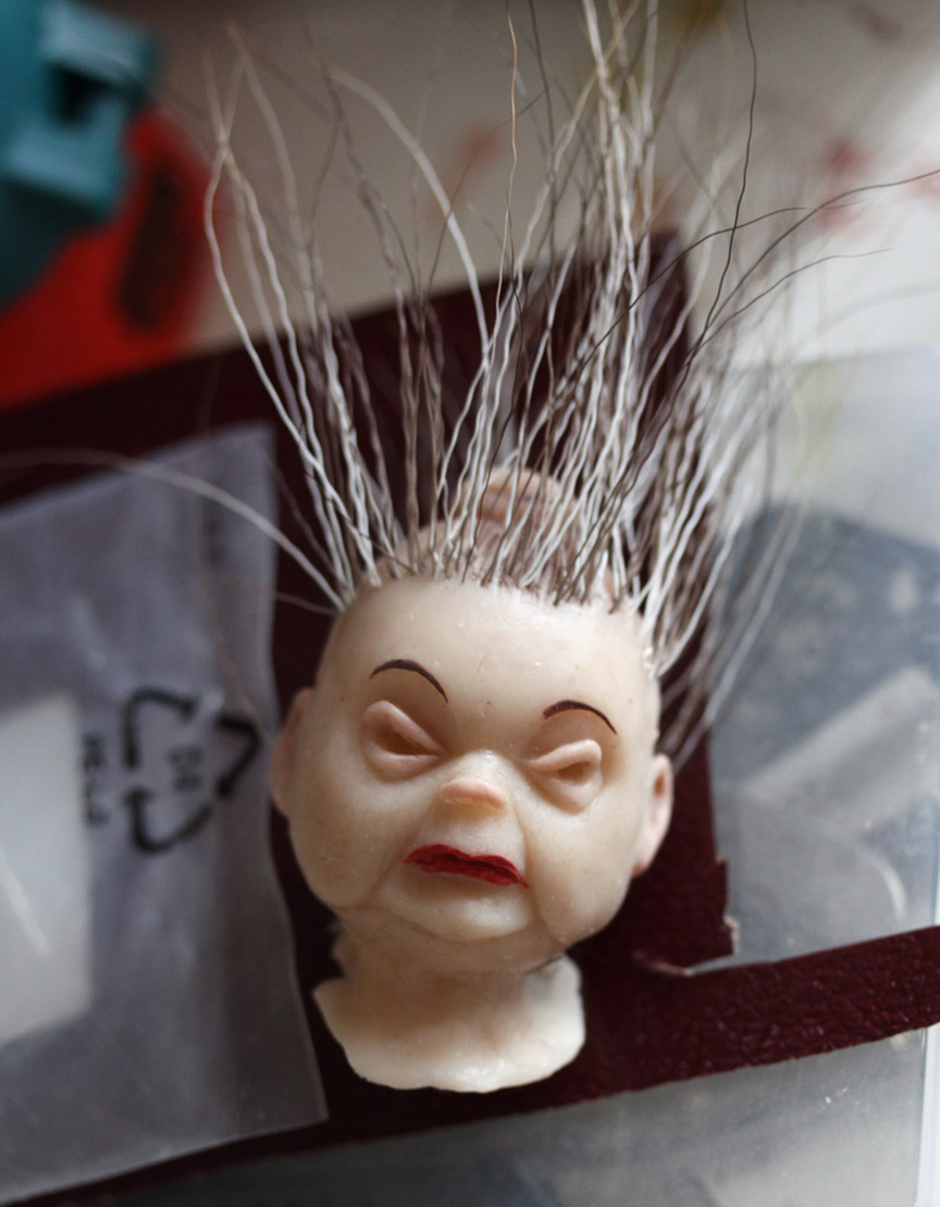
Image 7.
Animating clothes using poseable fabrics.
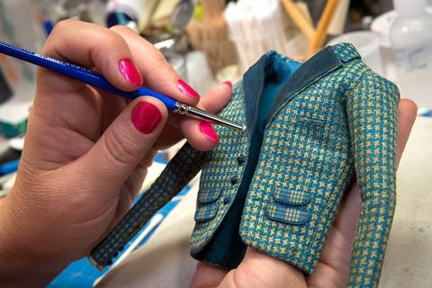
Image 8.
Screw fixings at the soles of the feet.

Image 9.
What are the benchmarking standers for armatures in industry?
Bench marking
Armatures vary in complexity depending on how it will be used and the character it's for.
A wire armature is the most simple of sorts. Using aluminium wire is best as it can take the most amount of bends without breaking. Armatures are not just made for stop motion characters, wire armatures are mostly used for sculpture.
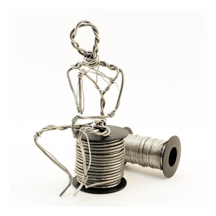
Image 10: most simple wire armature.
Aluminium wire armatures for stop motion usually look more like these three. Milliput is sculpted or thin brass tubes are placed in the parts that are not supposed to bend, dividing bone from joint. Wire fingers are positioned evenly into the palm of the hand which is made out of Milliput giving them hand armatures. One or two double ball & socket joints are used for the neck and two steel or brass plates are used for the feet often with a hinge in each separating toe from heal. These will have screw points in for mounting the character in position.

Image 11: Advanced aluminium wire armature.
Ball & socket armatures are the most used in industry. Unlike wire ball & socket joints wont break over time and they are also mechanical fixings using screws so everything replaceable. This armature consist of 12 double ball & socket joints giving the armature 2 pivoting parts for each joint. This armature is completely made out of steel but for the joints the ball's must be a harder steel than the plates to prevent them from getting distorted and not being able to rotate all around.

Image 12: Advanced ball & socket armature.
Steps
Out sourcing & armature designing
In my learning agreement I gave myself from the 1st to the 31st March to complete the construction of the armature. Now that the time has passed I can say I completed my goal :)
I began by purchasing an STL zip file of K-VRC in parts. Once I had assembled the parts in Rhino and made him complete I thought about the scale I should make him to.
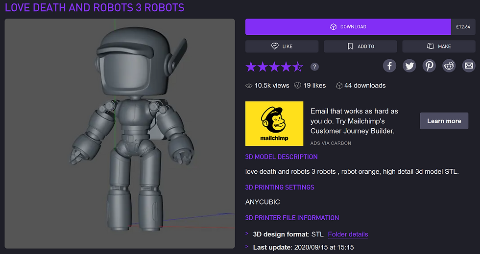
Image 4: STL zip file of K-VRC
2. The character is tiny in comparison to his companions so I thought making him 1 to 8 or 1 to 6 would be too small. I put this to the test by matching the height of K-VRC to the height of a toddler and then dividing that size by 6. The general height of a toddler is 850 mm, divided by 6 gives me 142 mm which is my 1 to 6 scale. I still thought it was too small for the intricacy of this character so I decided that I would make him 180 mm tall giving me the few extra millimetres for those intricate parts.
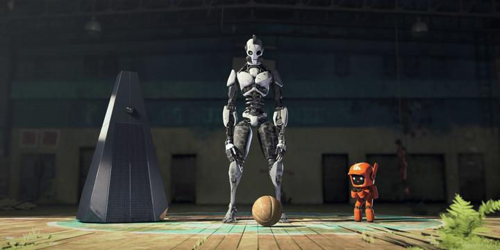
Image 5: Tiny orange robot
3. I split the character down the middle leaving only his left side. This was the most efficient way to start designing the armature. By gauging the proportions of the left side of the body I could create a CAD model of the right side of the armature to fit perfectly.
4. Now that I had reached this step I started to visualise the possibility's to the characters movements. I needed to decide where his joints will be placed to facilitate the most amount of movement.
Each shoulder needed two joints due to the head being so large. two ball & sockets and two pivoting joints make up both shoulders..
Elbows, knees and the second shoulder joint will need to be pivoting joints as these will be exposed replicas of the characters joints in the animation.
There will be 9 interior ball & socket joints for the neck, shoulders, waist, hips and feet.
Due to the small scale of the armature the ball & socket joints will be singular instead of doubles. I'm hoping by the way I design the armature this shouldn't constrict his movement as a stop motion character.
5. I started by modelling the characters exposed pivoting joints. These are the joints that will be on show so they need to be as precis as possible. I created technical drawings of each of these joints for me to work from.
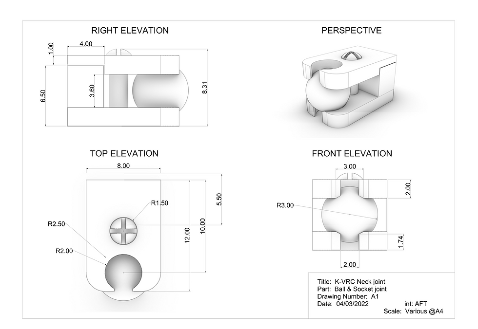
Image 4: Single ball & socket joint X9.

Image 5: Shoulder pivoting joint.

Image 6: Elbow pivoting joint and wrist ball & socket joint.

Image 7: Knee pivoting joint.
6. All there was left to do was to position the joints in symmetry with the left side of the body and connect them together to form a complete armature design.
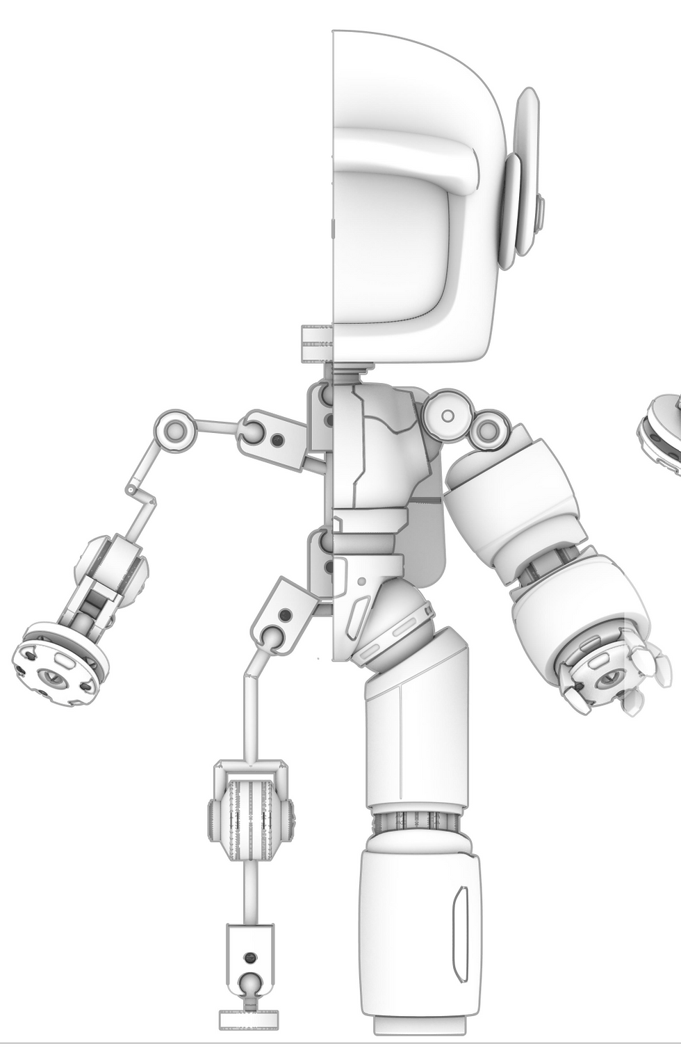
Image 8: completed armature CAD design.

Image 9: complete armature technical drawing.
Image 5: https://www.tctmagazine.com/additive-manufacturing-3d-printing-news/famous-faces-3d-printing-laika/


Comments